
Leading the Charge: The Future of Electric Vehicle Charging Stations
Unpacking the Infrastructure Investment and Jobs Act
Mar 07, 2022
Principal Wesley Lau, PE, LEED AP & Associate Kim Wall, PE, LEED Green Associate
The government is betting on electric vehicles in a big way. On November 15, 2021, the Infrastructure Investment and Jobs Act (H.R. 3684) became law, providing $5 billion from 2022 through 2026 for states to deploy electric vehicle charging infrastructure and collect data on its use. Through this law, the government aims to greatly expand electric vehicle access and usage nationwide and promote an already growing fleet of electric consumer and commercial vehicles.
Summary of H.R. 3684
National Electric Vehicle Formula Program
(H.R. 3684—993) Under the law, states are allowed to allocate funds to:
- The acquisition and installation of electric vehicle charging infrastructure. This is a catalyst for the deployment of the infrastructure and will connect it to a network to facilitate data collection, access, and reliability.
- Proper operation and maintenance of electric vehicle charging infrastructure.
- Data sharing about electric vehicle charging infrastructure to ensure the long-term success of investments.
The two major stipulations are that the proposed electric vehicle infrastructure is available to the public or authorized commercial vehicle operators, and the infrastructure is located along a designated alternative fuel corridor. These alternative fuel corridors are stretches of highways that the government has chosen to support alternative fuels—electric, natural gas, propane, and hydrogen. There are multiple corridors in most states, and the list of current candidates for these corridors is available on the DOT website.
Second-Life Applications for Electric Vehicle Batteries
(H.R. 3684—518) In addition to funding for electric vehicle charging stations, there are funds available for studying second-life applications of electric vehicle batteries. Awareness and concern over the waste created when an electric vehicle battery no longer carries enough charge to be useful to the vehicle and must be replaced has prompted a study seeking solutions for these batteries, specifically as aggregate energy storage installations to provide services to the electric grid. Specifically, the intentions of the study include:
- To demonstrate the ability of electric vehicle batteries to provide ancillary services for grid stability and management and reduce the peak loads of homes and businesses.
- To extend the useful life of electric vehicle batteries and the components of electric vehicle batteries prior to the collection, recycling, and reprocessing of the batteries and components.
- To increase acceptance of, and participation in, the use of second-life applications electric vehicle batteries by utilities.
The results of this study will bolster the use electric vehicle batteries to solve the growing issue of grid load management, as utility grids are coming under increasing strain due to the increase of renewables (solar and wind) for energy generation. These resources, while they increase the overall capacity of the grid, create issues when generation suddenly drops (i.e. the sun sets, winds cease) but demand remains steady.
A related issue is addressing the peak load times. Utilities must build enough generation to handle the peak loads, but these assets are often underutilized throughout the year. This results in unnecessarily higher energy costs and a greater carbon footprint. Second-life electric vehicle batteries can address both issues as they help fill in the valleys and cut down the peaks experienced by the utility grid. This allows for more reliable, greener power for consumers and likely a greater demand for electric vehicles, as it potentially lowers the cost of battery replacements.
Vehicle-to-Grid
(H.R. 3684—615) Additionally, funds within the bill support a study to expand data collection with respect to electric vehicle integration with the electricity grids. Vehicle-to-grid (V2G) is a technology that enables electric vehicles to store and push back energy to the utility grid based on the grid demand. This results in utilities having access to the batteries of the thousands of electric vehicles that are idle for much of the day as a kind of distributed battery bank. This not only helps to resolve some of the issues addressed by the second-life battery banks, but because the resource is distributed, it can improve transformer loading congestion and distribution-system congestion, reducing the need for additional utility infrastructure. The result for the consumer is a low-cost, greener energy as well as a direct economic discount or payback to those who make their vehicle available.
These welcome measures will lead to a greater demand for electric vehicles and more support industry-wide for electric vehicles, which will increase savings on electric vehicles and reduce energy costs for all!
Requirements for the National Electric Vehicle Formula Program
There is $5 billion in funding available for states and other agencies to build electric vehicle charging infrastructure through the National Electric Vehicle Formula Program (NEVFP). In order to take advantage of these funds, the infrastructure:
- Must be located along a designated alternative fuel corridor.
- Must use non-proprietary charging connectors.
- Must use open access payment methods that are available to all members of the public.
There are several non-proprietary charging connectors commonly used on the market today. These include SAE J1772 for Level 1 and 2 charging and SAE Combo Combined Charging System (CCS) and CHAdeMO for Level 3 charging. These chargers are explained in more detail below.
The three biggest open access payment methods in the U.S. are operated by EVgo, ChargePoint, and Electrify America. We recommend contacting these companies during design to obtain specifications of the most current charging stations available.
Tesla plans to open their Supercharger network to other electric vehicles. and they have started their pilot project in the Netherlands. However, until this is implemented in the US, the Tesla proprietary connectors and payment system are not eligible for NEVFP funds.
EV Chargers and Infrastructure
Types of Chargers
There are several types of EV chargers available currently, designated by Levels per the Department of Energy. Consideration of types of charging needs goes along with evaluating the electrical requirements of each type.
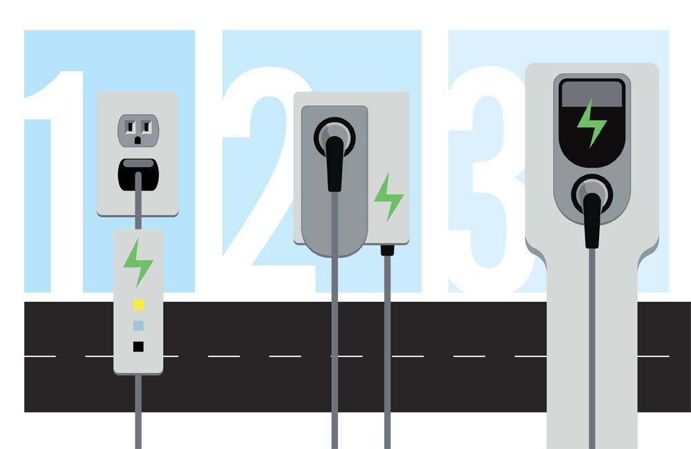
Level 1 chargers are the most basic, typically connecting to a 120V receptacle and 2 to 5 miles of range per hour of charging. Typically, upon purchase of an EV, a Level 1 cordset is provided which has the standard 15 or 20A plug on one end and a SAE J1772 standard connector on the other.
Level 2 chargers are the most common in the US, and covered 80% of the public EV charging stations in 2020. Level 2 chargers connect to a single phase 208V (commercial) or 240V (residential) system and provide 10-20 miles of range per hour of charging. As most buildings, both residential and commercial, have 208V or 240V systems, the increased charging speed elevates the Level 2 charger’s popularity. Generally, Level 2 chargers can fully charge a battery overnight. There are several options with Level 2 chargers, including amperages available which affect the delivered power to the vehicle and station configurations such as quantity of connectors. The Level 2 chargers utilize the SAE J1772 connectors, but are generally permanently connected to the station, not a separate cable provided with the vehicle. Manufacturers with proprietary connectors, such as Tesla, typically come with a SAE J1772 adapter allowing them to utilize the Level 2 chargers.
Level 3, or DC Fast Charging, are growing in popularity, especially along highways and interstates. As the name indicates, these chargers provide the highest ranges for the shortest charging times, 60-80 miles in 20 minutes. With this increased charging speed, the electrical connection also increases in size, requiring a 208V or 480V, three phase connection. Under the DC Fast Charging umbrella there are three types based on the charging port connector; SAE Combined Charging System (CCS), CHAdeMO, and Tesla.
The SAE Combined Charging System (CCS) utilizes the same SAE J1772 connectors as Level 1 & Level 2 chargers, the only difference being two added bottom pins on the connector to support the DC charging. Currently, not all EV’s come with a CCS compatible connector, however an increasing number of manufacturers are moving to make CCS the standard in the US.
CHAdeMo are the most common type of DC Fast Chargers. CHAdeMo charging was designed to accommodate bidirectional charging, which is popular in Japan.
As mentioned previously, Tesla’s unique proprietary connector works for all types of charging connections (Level 1, 2 and DC). Tesla offers a CHAdeMo as well as the J1772 adapter, and they also have a CCS adapter for new vehicles. Tesla also has proprietary charging stations, called Superchargers, available for installation and throughout the country. Currently, Tesla is the only available DC Fast Charging station for residential installations.
Electrical Requirements
While developing the project requirements around EV chargers, it is essential to evaluate the electrical system, both for new and existing infrastructure.
The primary difference between the various chargers is where the conversion from AC to DC is made. Level 1 and 2 chargers rely on the vehicle for the AC to DC conversion, where its on-board charger regulates the charging speed. The speed is dependent on the vehicle’s specific capability of receiving AC from the charging station and converting the current to DC to charge the batteries. Level 3, or DC Fast Charging, removes the speed limitations of the on-board charger by by-passing it completely and providing the DC power directly to the vehicle’s batteries. Since the Level 3 charger is doing the conversions from AC to DC the charging speed is greatly increased.
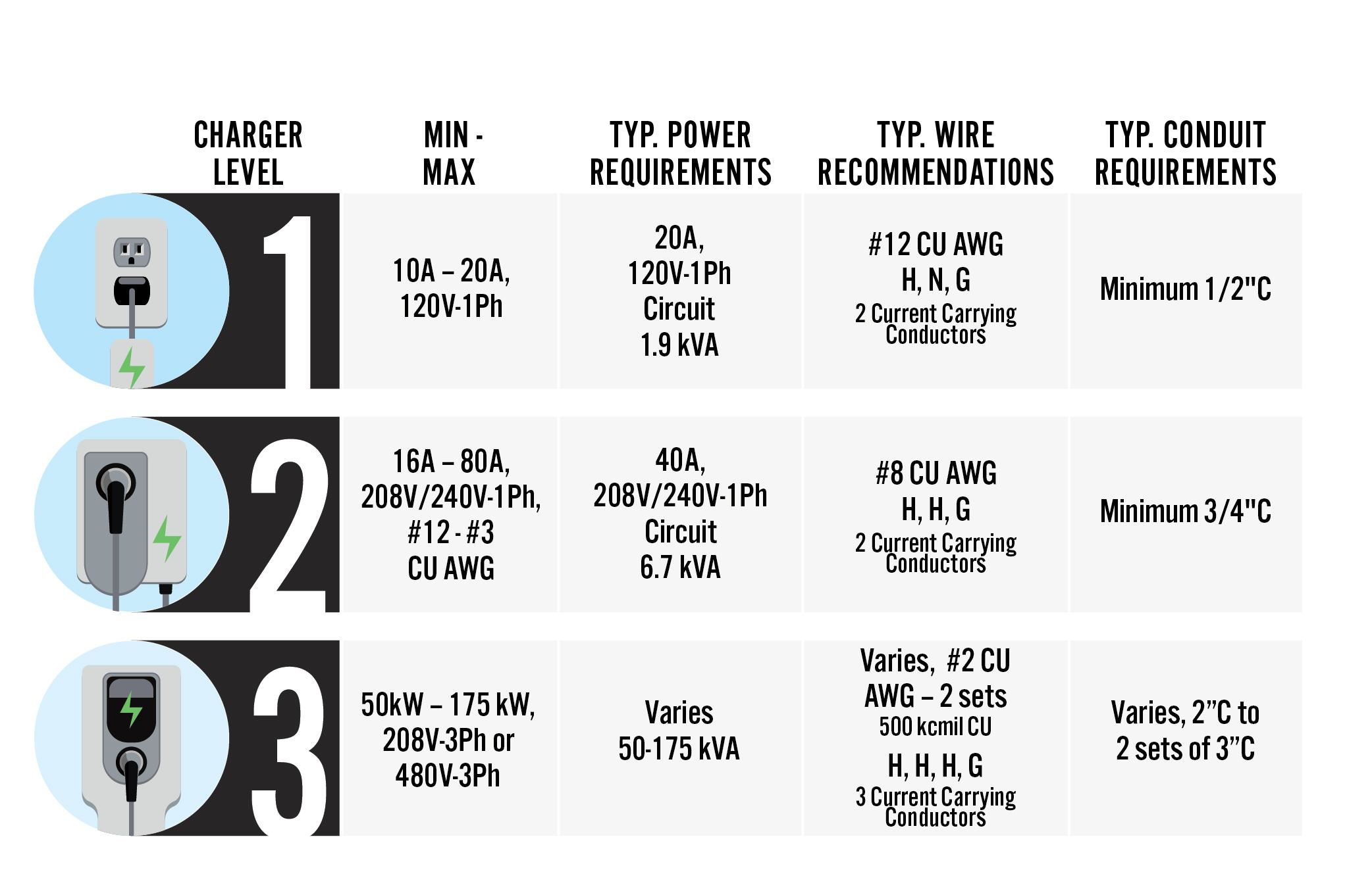
Level 1 chargers, have the slowest charging speeds, but are the easiest to incorporate into any electrical system. Only a standard 15A or 20A receptacle is required. When designing an electrical system to include designated Level 1 charging locations, a dedicated 120V, 20A circuit per receptacle should be provided to account for the variety of readily available charging cable, ranging from 10 to 20A.
There is a larger variety of Level 2 charging stations readily available on the market, all requiring a single phase 208V or 240V connection. When incorporating Level 2 chargers into your electrical system, it is important to consider the additional capacity as well as additional panel/breaker space required. Residential products range from 16 amps to 50 amps, with varying charging speeds. Commercially available products have a wider array of options, including quantity of connectors, shared power options, and amperages ranging from 16 amps to 80 amps. The most common type of Level 2 charger uses a 40A, 208V/240V-1Ph circuit.
Level 3 or DC Fast Chargers require the largest electrical demand and are typically utilized by specialized public or government facilities. This equipment needs a 208V or 480V, three-phase connection with a range of 50kW to 175kW.
Additionally, increasing the size of conduit is permitted and will provide an easier installation with minimal cost implications. The NEC (National Electrical Code) indicates minimal burial depths based on location of wiring; such as under driveways and parking lots. Permitted uses for each type of conduit (EMT, PVC, RMC, etc) is also dictated by the NEC. Finally, consider how many wires each charger requires, especially when looking to utilize shared conduit, above (3) current carrying conductors within a conduit, the allowable amperage will have to be derated per the NEC.
The following summarizes the typical power requirements for each level:
Load Readings Recommended
When installing new electric vehicle chargers at an existing site, it is important to confirm there is capacity in the existing electrical service. If as-built electrical drawings are available, the original electrical load calculations can be consulted to see what the available capacity (kVA) is.
However, commonly the original as-built electrical drawings are not available, or there have been multiple renovations since the original drawings were created. In this case, there are two other options. If utility bills are available that show the maximum electrical demand per period, the maximum demand from a 1-year period is permitted to be used in lieu of the calculated demand.
If utility bills showing maximum demand are unavailable, an electrical load reading can be conducted at the service and at the point of connection in the electrical distribution system. A load reading typically requires a brief electrical shut down, during which a licensed electrician will install temporary current transformers (CTs) in the electrical panels to measure the actual electrical load. The length of time ranges from 3 days to 30 days depending on the requirements of the local Authority Having Jurisdiction (AHJ). The maximum demand recorded during this time period can be used in lieu of the calculated demand.
Whichever method is used (utility bills or load readings), the National Electrical Code (NEC 220.87) permits installations where the sum of the existing demand multiplied by 125% and the new load does not exceed the capacity of the electrical service. An Interface Engineering electric engineer can be consulted to perform these calculations.
Technology Requirements
Commercial electric vehicle chargers need to communicate with their network in order to provide tracking and payment services. Most charging manufacturers offer hardwired (ethernet), Wi-Fi, and cellular options for communication.
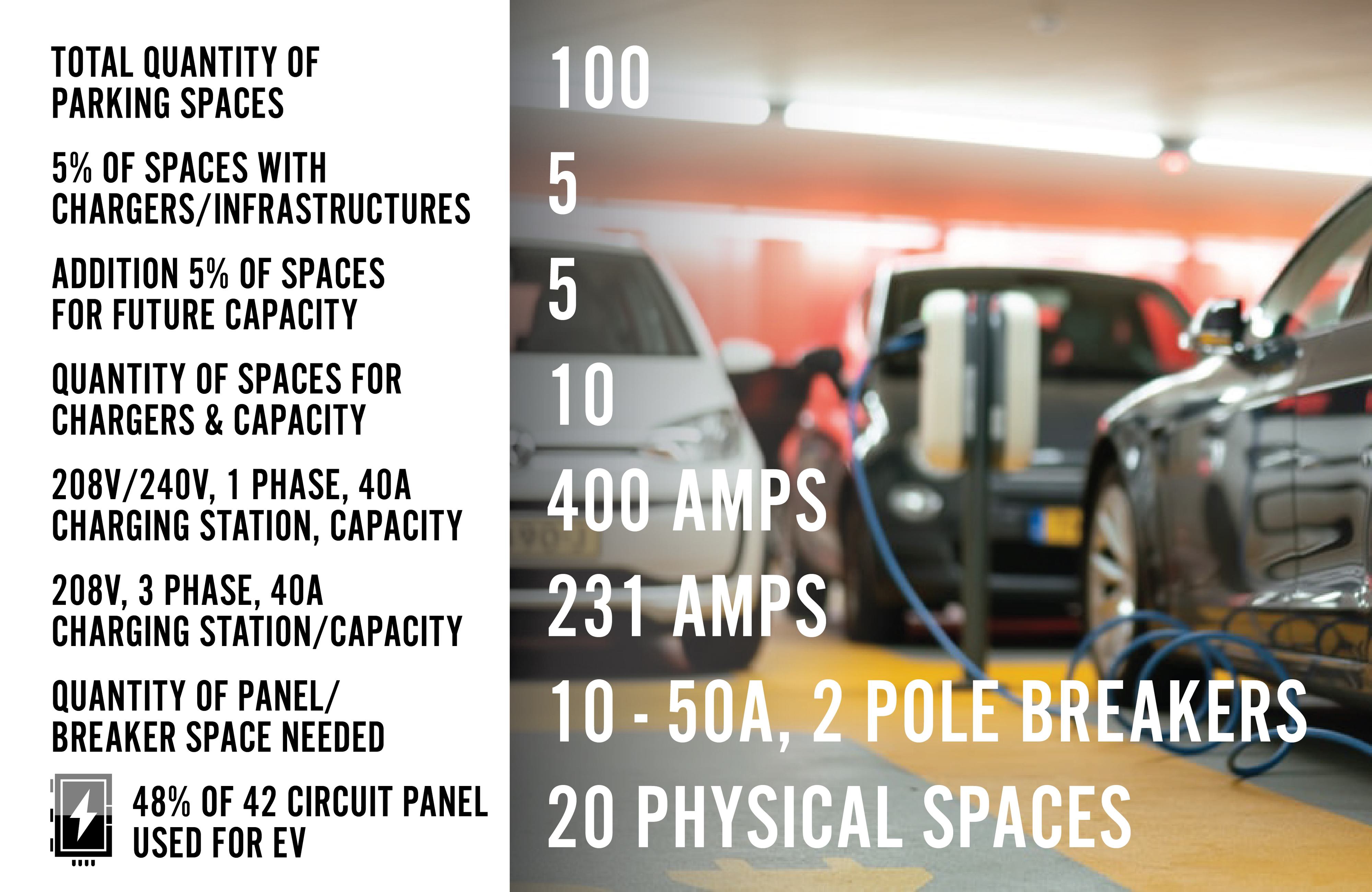
Commercial Case Study
An owner/developer of a new commercial office building is requiring a minimum of 5% of parking for EV charging stations within their project requirements. In addition, the owner is also requiring capacity additional 5% of parking to be included in the electrical distribution system for future installation. A 40A, 208V basis of design charger has been selected. If the new building is provided with 50 parking spaces, an additional 400A of capacity will need to be incorporated into the distribution system as well as a minimum of 10, 2-pole circuit breakers, or 20 breaker spaces. The additional capacity and breakers should be considered when laying out your electrical equipment. Pathway out of the building for future chargers should also be evaluated during design. Providing a flush grade handhole and conduit back to the electrical room will aid in the installation of future chargers. As you can see, EV chargers could have a large impact on the building’s electrical distribution system as well as the space required for the equipment.
Rest Stop Case Study
An existing rest stop operator is tasked with evaluating the electrical implications of adding a few new Chargers. Project requirements are to provide (2) Level 3 (DC Fast Charging Stations). A 75 kW Charging Station has been selected as the basis of design.
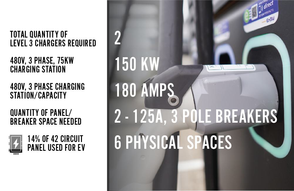
After evaluating the added load from the new in addition to the existing peak demand load on the service, the operator determined that their existing distribution system was adequately sized to support the chargers.